High-Precision Brushless Motor Rotor Magnet
Why the magnet decides torque ripple
A brushless motor's torque ripple, cogging and efficiency are decided at the magnet, not at the controller. This page is for engineers specifying rotor magnets for brushless DC motors, PMDC motors, e-bike hub motors and robot-vacuum traction motors. We produce the arc and tile segments, the Halbach layouts and the assembled rotor sub-systems that go into them.
Grade first, then flux
Rotor magnets run hot, and grade selection should start from the operating temperature rather than from the highest available flux. The temperature ladder is: N series up to 80 °C, M up to 100 °C, H up to 120 °C, SH up to 150 °C, UH up to 180 °C and EH up to 200 °C. For a rotor that will soak in a hot housing, an SH or UH grade is usually the right answer; the trade-off is a small loss of flux against the room-temperature grades.
Geometry: arc segments and Halbach arrays
We make arc and tile segments to drawing for radial rotors, curved arc OEM geometries, and multi-segment Halbach arrays where the magnetization pattern rotates by a fixed angle from segment to segment instead of pointing straight at the axis. Magnetization direction is not limited to a single pole: radial, axial, diametral and custom multi-pole patterns are all available, and we build dedicated magnetization fixtures for rotor work so the pattern is reproduced part to part.
Tolerance and assembly
Standard dimensional tolerance is ±0.05 mm, which is what a rotor stack normally needs so that segments seat without rocking; where a drawing calls for tighter control, critical dimensions are held to ±0.02 mm using grinding or wire-cutting. Because we also build the steel housing and the rotor sub-assembly, the magnet and the stack tolerance are controlled by the same process rather than negotiated between two suppliers.
Coating
Ni-Cu-Ni is the usual choice for a rotor that will be handled during assembly and see condensation; epoxy is used where a motor is expected to see humidity or a wash-down environment. Salt-spray duration is matched to the coating across a 12–96 hour window rather than fixed at one number.
Lead time and samples
Samples run 10–15 days, small batches 20–30 days and mass production 40–60 days. In-stock samples are free of charge — you pay only the freight. Send the rotor OD/ID, the segment count, the operating temperature and the required flux, and we confirm feasibility within one business day.
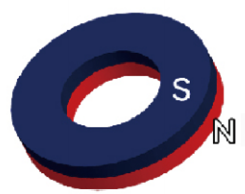
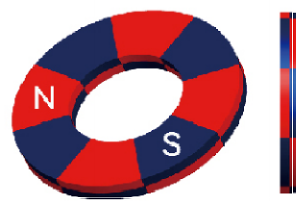
Available magnetisation directions — Ring magnets
The magnetisation direction is fixed when the magnet is magnetised and cannot be changed afterwards, so the direction must be confirmed before production.



Manufacturing capability & measured data
Tolerance
- Standard production
- ±0.05 mm
- Critical dimensions (on request)
- ±0.02 mm
Quoted per dimension against international dimensional quality standards, not as one blanket percentage. ±0.05 mm is the standard band; where a drawing calls for more, critical dimensions are held to ±0.02 mm using grinding or wire-cutting. The final tolerance is confirmed against your drawing before production.
Salt spray
- Duration depends on coating
- 12 – 96 h
Tell us how many hours your application needs and we match the coating to it. The test standard and the hours each coating reaches are confirmed on request.
Lead time
- Sample
- 10 – 15 days
- Small batch
- 20 – 30 days
- Mass production
- 40 – 60 days
Bands are by order type, not a single quantity threshold; exact lead time is confirmed at quotation.
Catalogue range and specialty grades
- Standard catalogue range
- N35–N52 (M–AH series)
- Specialty grade, on request
- N54 / N55
- Designation
- N54 (China) · N55 (international)
Related Products
- Custom Halbach Array Motor Magnets, N52 to N52SH
- Neodymium Magnets Segment Strong Performance
- High Temperature Resistance Neodymium Arc Magnet
- N42SH / N52H Arc Magnets for Motors
- Supported Curved Arc N52 N42H N35H Free Energy
- Strong Neodymium Magnets Curved Arc Tile Segment